

Taking off
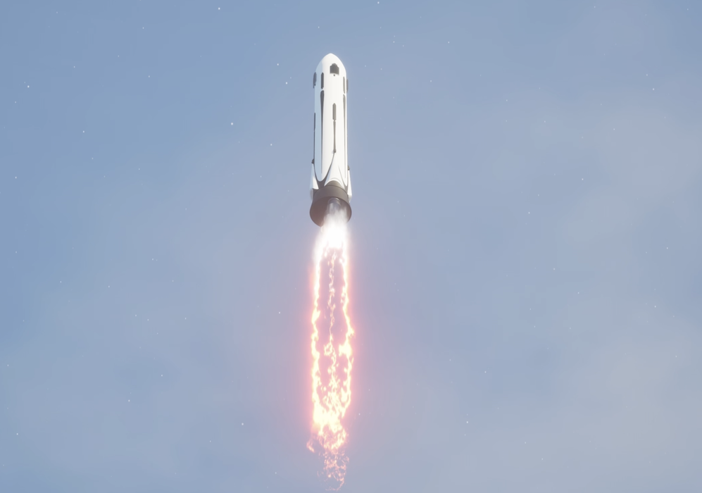
First, the demonstrator takes off. As it is fully loaded with propellant it is still slow at the beginning, but quickly gains more speed as the fuel is burned and it gets lighter, while the engines still provide all of their thrust. The flames of the engines are barely visible and slightly blue as the Prometheus® engines use Methane, in combination with Oxygen as propellants.
Main Engine Cut-Off (MECO)
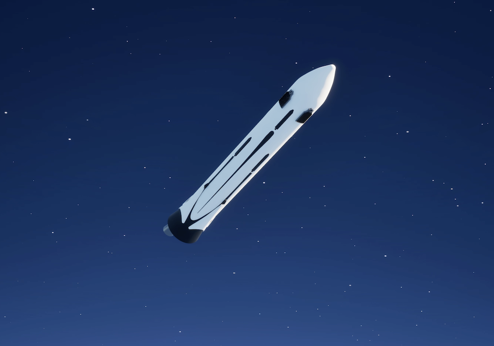
At higher altitudes, the surrounding pressure around the vehicle drops and therefore the plume of the engines widens. At an altitude of about 80 km the engines are shut-down: this is called the Main Engine Cut-Off (MECO). In this phase, the second stage would be separated for an operational launch vehicle.
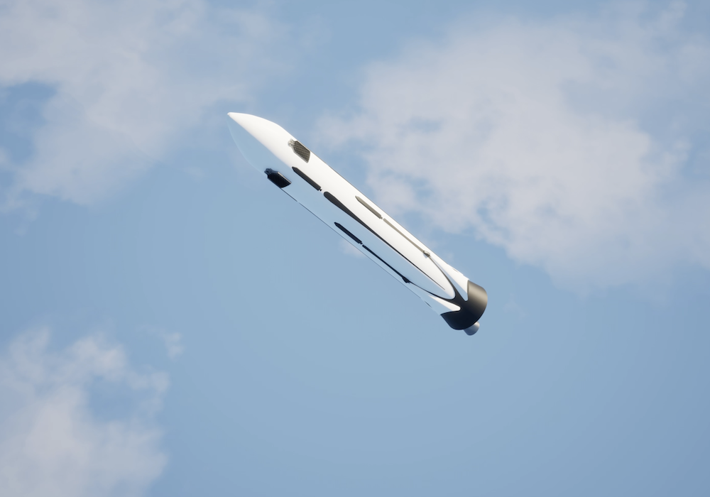
Flip-over maneuver
The next phase of the T3 flight follows immediately, which is the flip-over maneuver. In this phase small thrusters (the Reaction Control System) are used to reorient the vehicle, to “flip it”, so that it will be oriented with the engines first. In this phase, the vehicle follows a ballistic trajectory and the aerodynamic forces are still very low, so that it is comparably easy to turn the vehicle around. The grid fins would be deployed during this flight phase, as the forces are still low. The grid fins are small “wings” on the side of the launcher used to steer the vehicle later on.
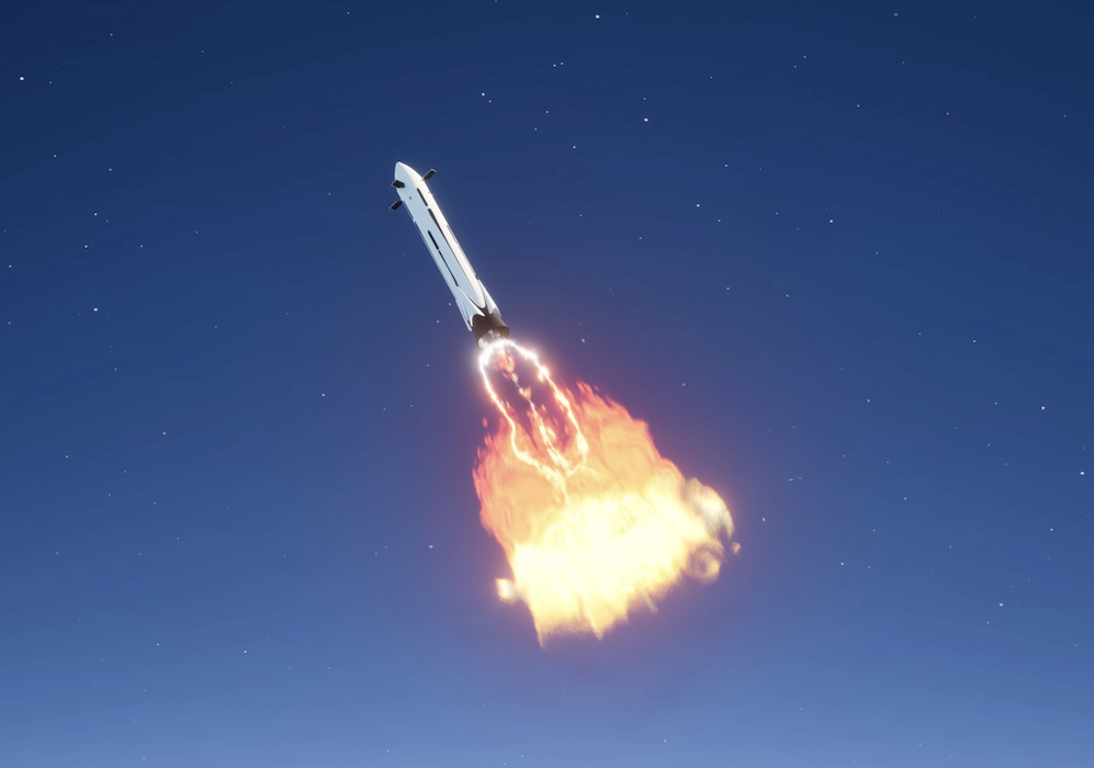
Re-entry burn
As the vehicle gained a lot of speed during ascent, while re-entering in the atmosphere, the vehicle would experience high heat loads (high temperatures) and the aerodynamic forces would be high. To reduce these loads, a braking maneuver is performed after the ballistic phase. The engines are fired against the flight direction of the vehicle to reduce its speed. This phase is called the re-entry burn. The number of engines used for this maneuver depends on several design decisions. In our case, we use two. Very specific highly fluctuating flow fields are formed in this phase.
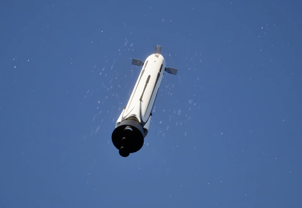
Aerodynamic phase
An aerodynamic phase follows the braking maneuver. This is a phase where the grid fins on the vehicle are used to steer it to the landing pad. As the vehicle is already in lower altitudes the pressure is higher and so the aerodynamic forces are high. Therefore, the easiest way to get the vehicle to the landing pad is by steering it aerodynamically. Touch down.
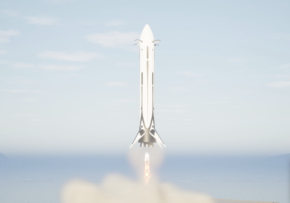
Touch down
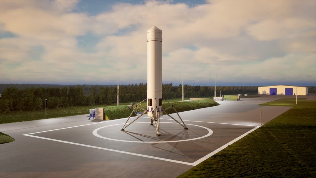
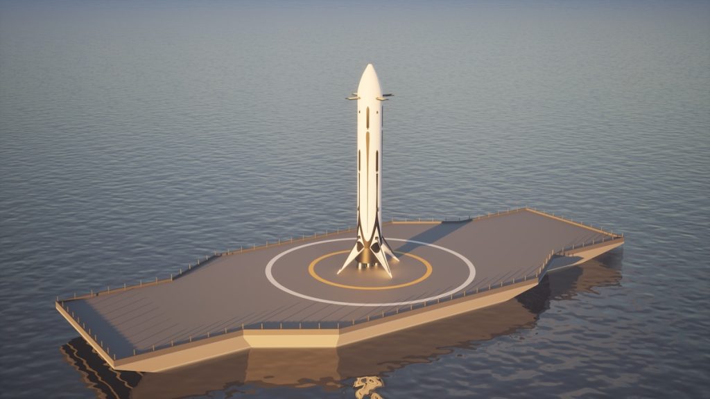
Finally, the vehicle landing is performed with one active engine. So that a soft touch down can be achieved, where the vehicle is oriented in a vertical manner. This maneuver is the so-called landing-burn. Shortly, before the touch down the landing legs are deployed.